


Many associations with the term “valve” exist. It is highly probable that, sooner or later, each of us will encounter this word.
There are as many associations as valve types. In this paper, we focus on control valves, which are devices operated in heavy industrial production plants, e.g. power plants, CHPs, refineries or chemical plants.
A control valve is an actuator device, which means that it regulates the flow of a medium in a pipeline according to the data received from a master device, e.g. a DCS (Distributed Control System).
Hence proper operation of a valve requires, first of all, an actuator and additional accessories. This paper describes the accessories installed on the control valves with pneumatic actuators (post and yoke types). The electric actuators installed on valves require no extra accessories.
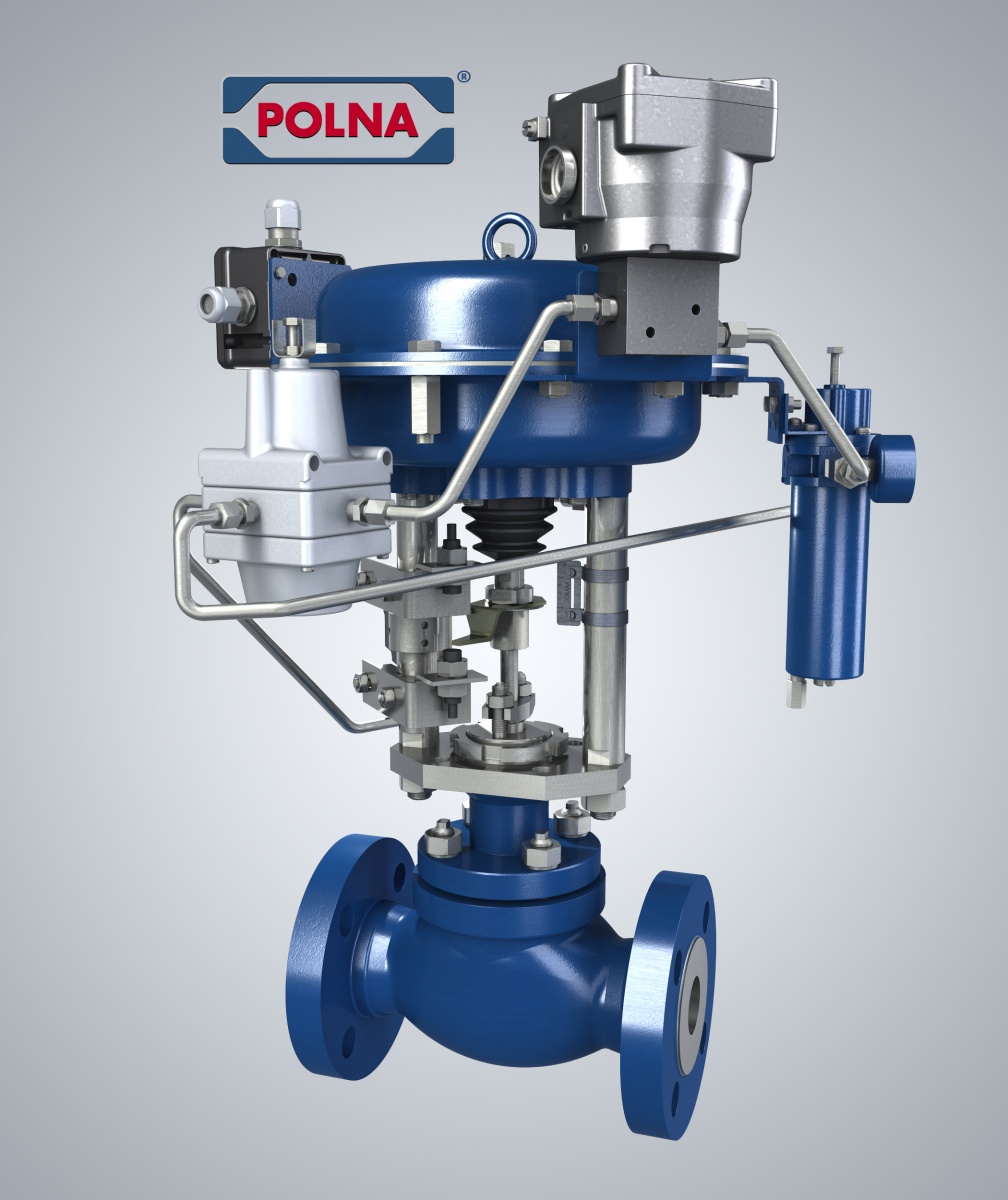
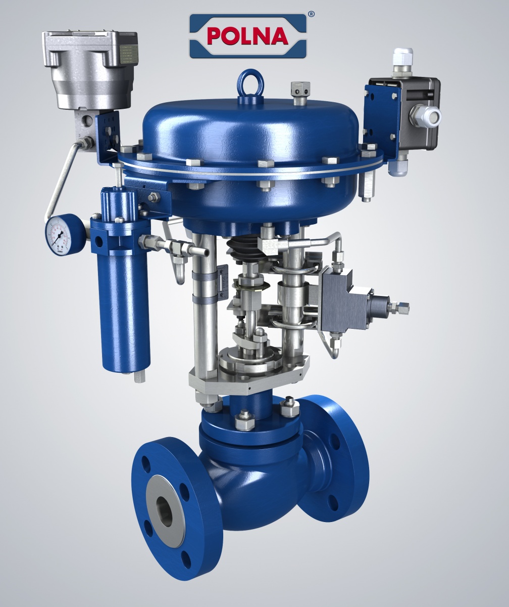
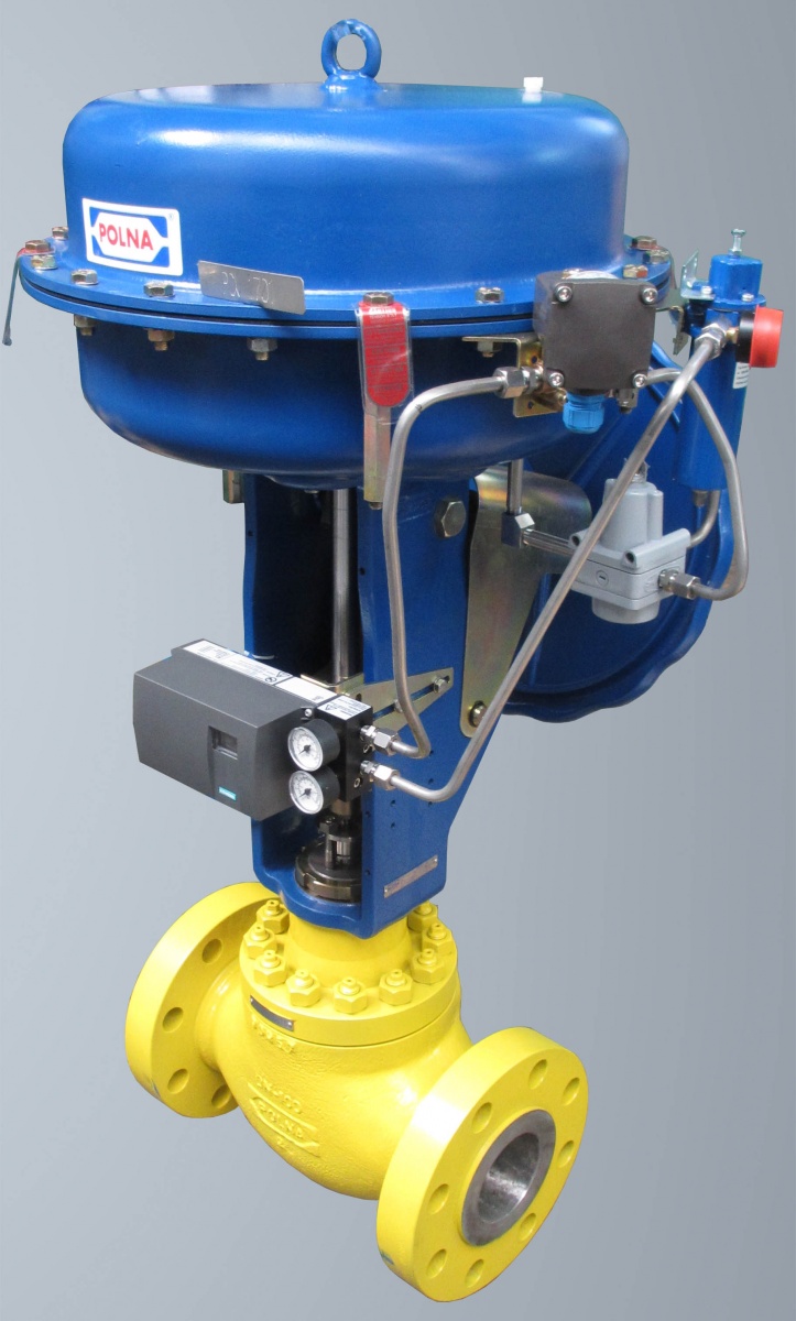
Fig. 1. Control valve with a pneumatic actuator and accessories (from the top: booster, airset and positioner).
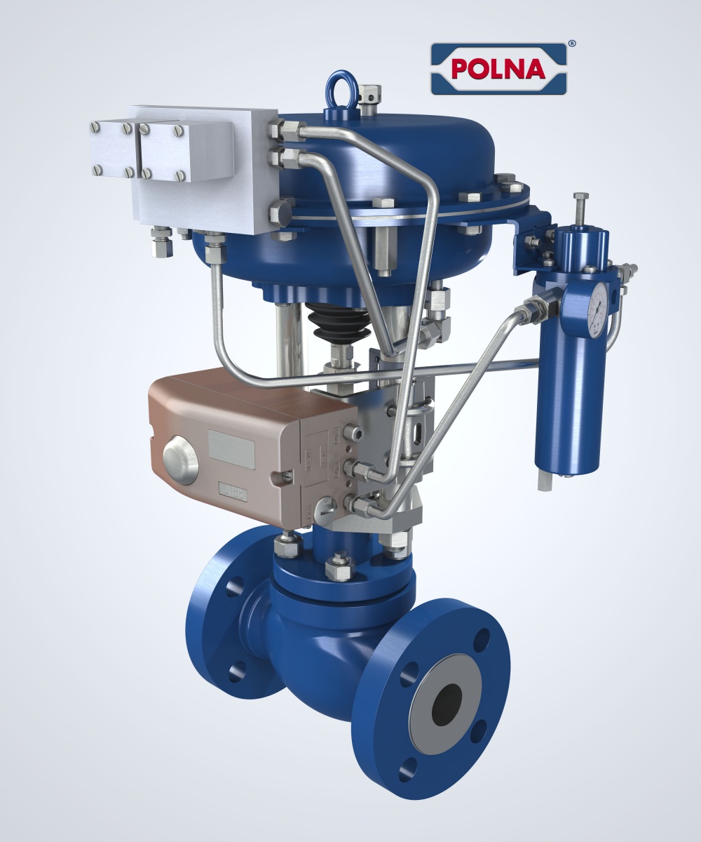
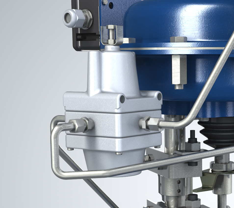
Booster: A booster amplifies the pneumatic signal. It also accelerates the time of actuator switching. It is used in applications which require short action time of the actuators.
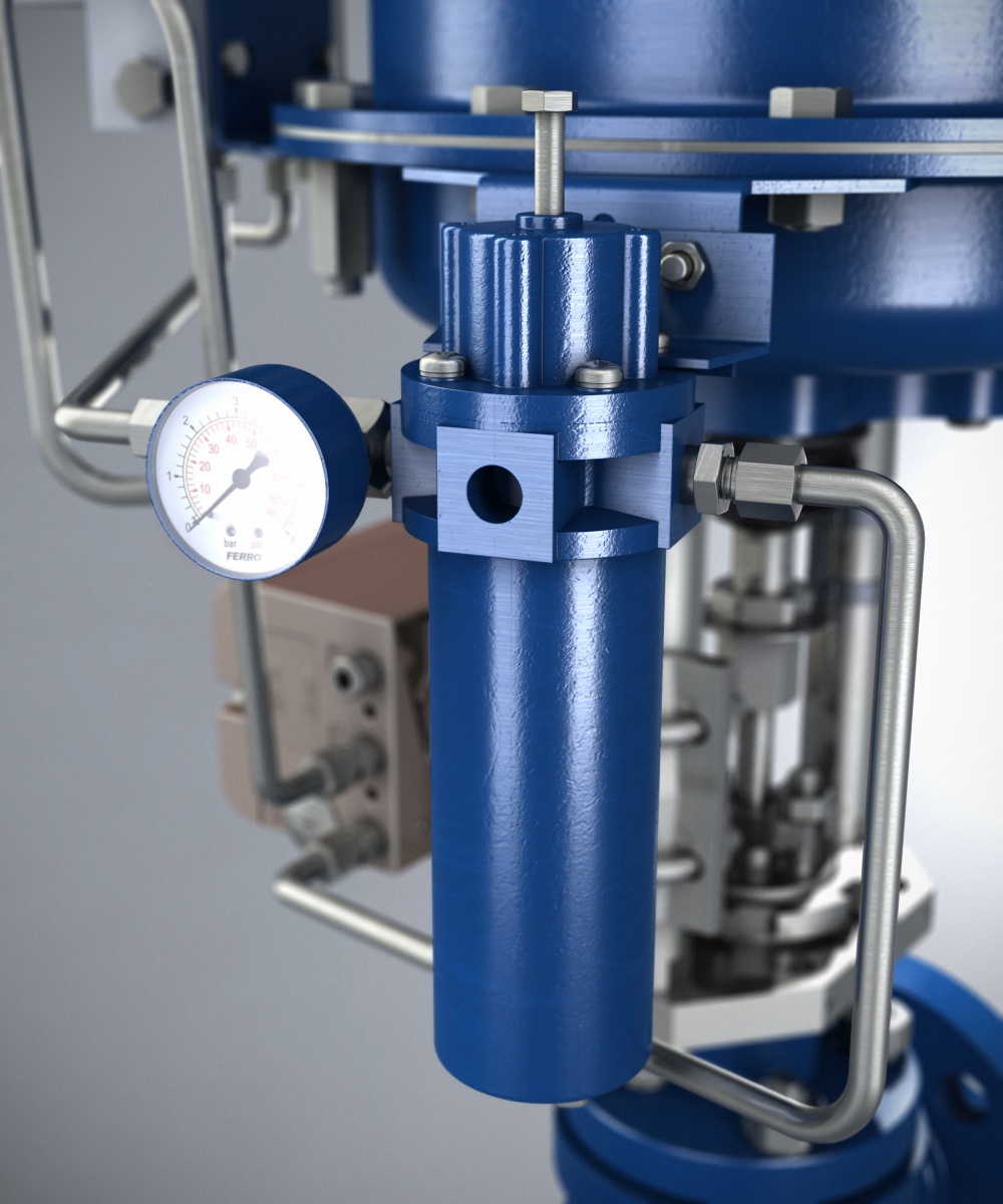 Airset:
An airset is designed to:
- adjust the air pressure supply of a pneumatic actuator to the required value
- clean the air from mechanical contaminants, oil and water.
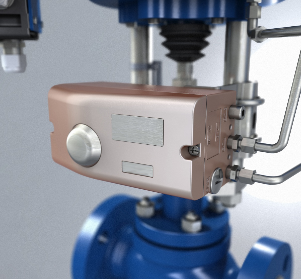 Positioner: A positioner is designed for setting the position of valve opening as required by the process by using a pneumatic or electric (analogue or digital) control signal. Positioners are used in pneumatic diaphragm actuators.
Positioners are recommended in the following cases:
- in systems which require high control accuracy,
- when the spring range does not correspond to the range of output signal from the controlling device.
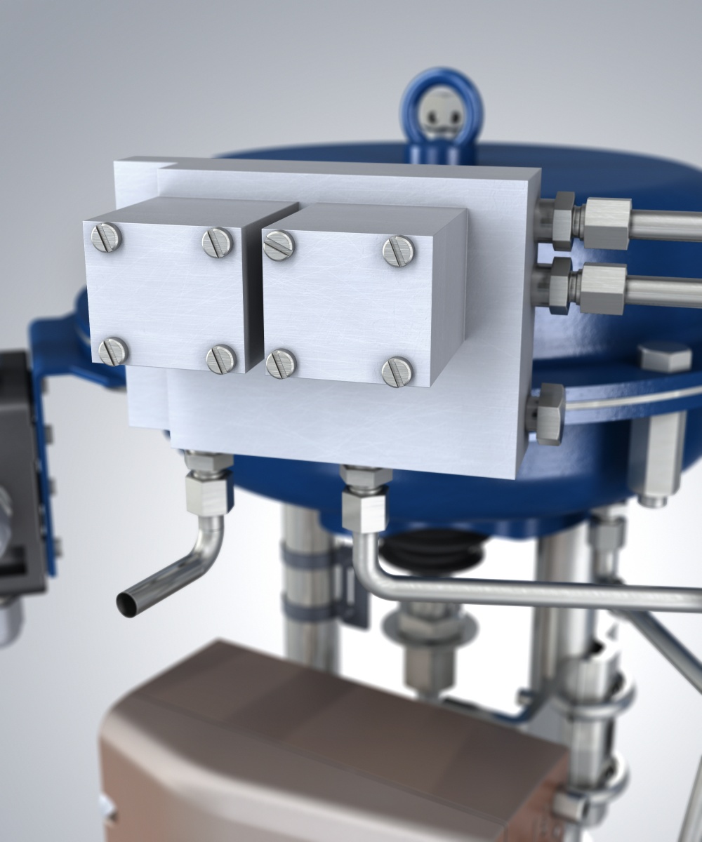
Fig. 2. Control valve with a pneumatic actuator and accessories (from the top: solenoid valve, lock-up valve, connection box, quick release valve, limit switches).

Solenoid valve: This valve type is controlled electrically. Solenoid valves are designed for opening and closing the supply of a control medium (air, in most cases) to the pneumatic actuator chamber by controlling the pneumatic signal. It is most often used in assemblies without positioners (on/off valves) or as an additional safety accessory. It allows for remote switching of the valve to its limit positions.
Lock-up valve: This valve is used in applications where, upon a failure (loss) of the pneumatic control signal, the valve must be stopped in the last working position.
 Quick release valve: A quick release valve allows reduction of the time to empty the actuator chamber in systems which require high speeds of valve opening or closing.
Limit switches: These devices indicate the preset limit positions of the valve.
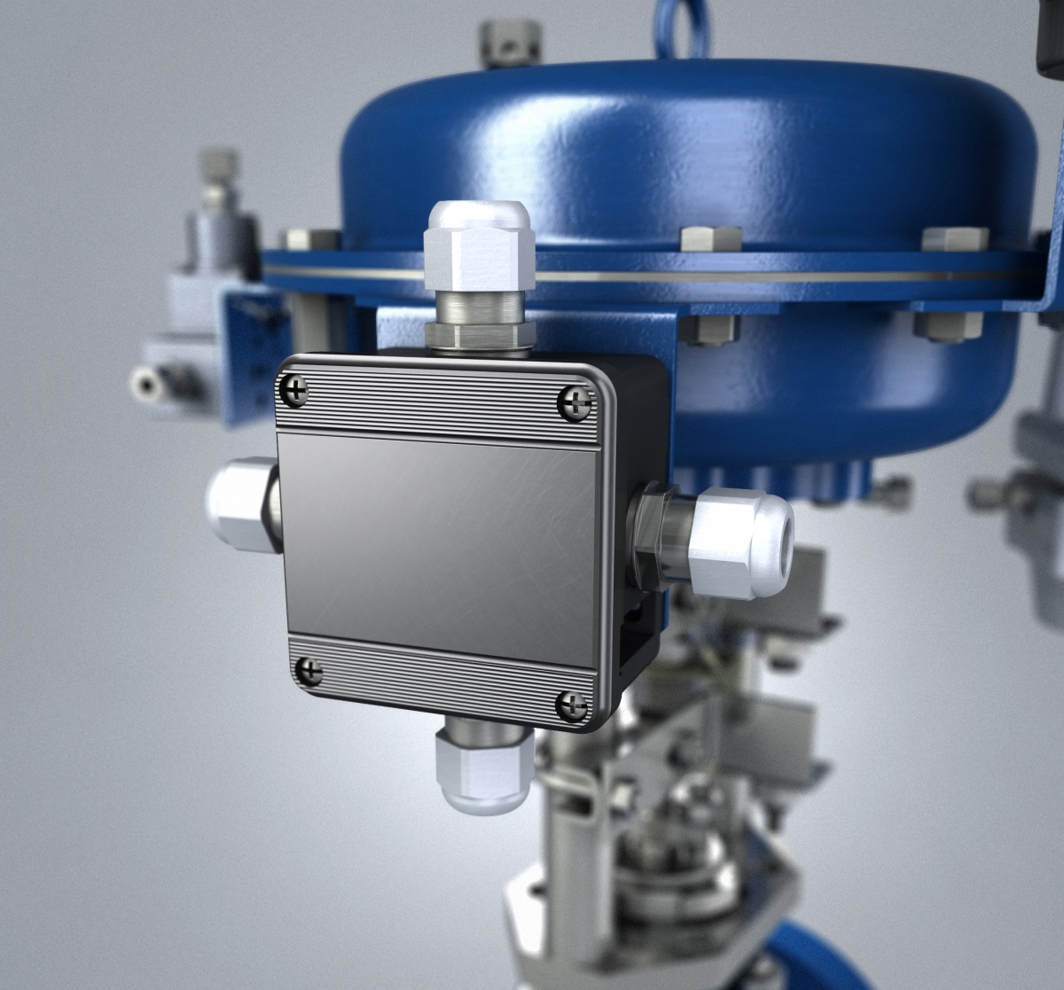
Connection box: It is used for connecting wires from valve-installed accessories with the field/facility wiring. Connection boxes are used most often with valves operated in explosion hazard zones.
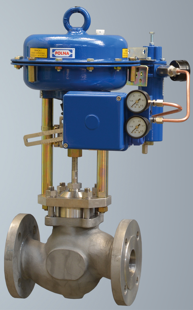
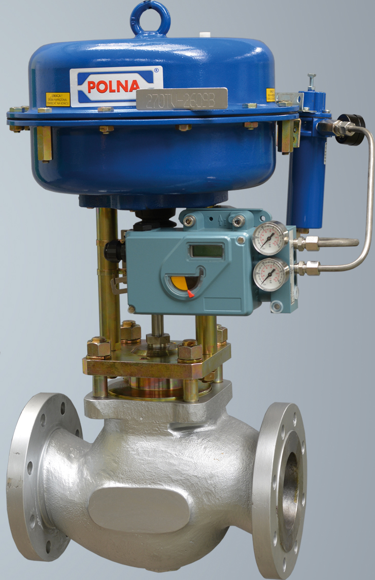
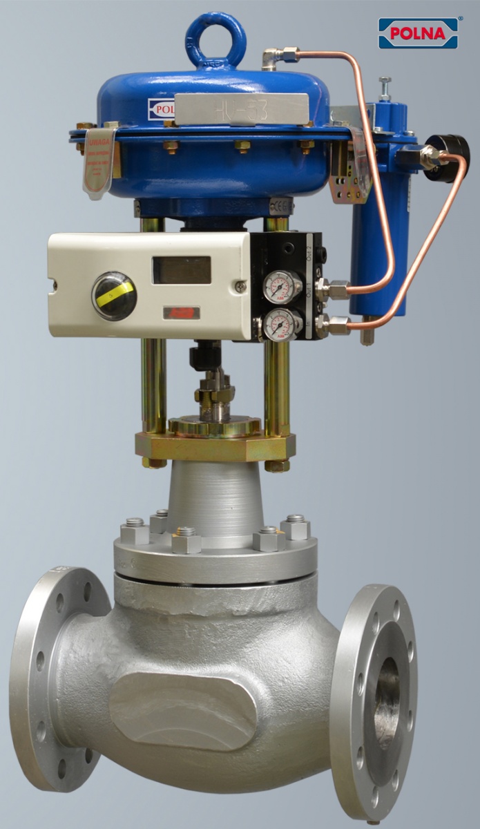
The following images show control valves with pneumatic actuators and additional accessories. The valves are ready for installation on a pipeline.
The valve assembly has a lock-up valve, a solenoid valve, an airset and a positioner.
The valve assembly has a booster, an airset and a positioner.
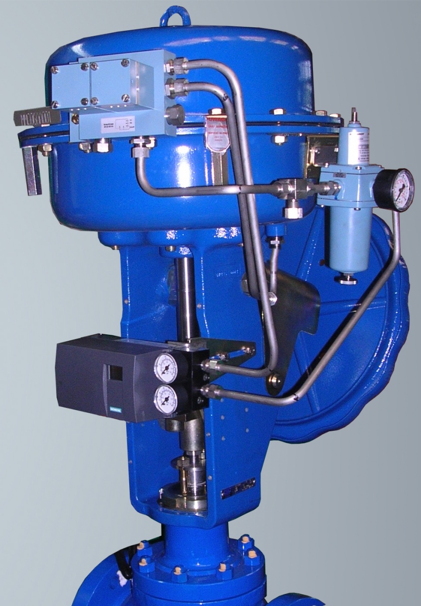
The following images of control valves show the positioners of various brands used in valve assemblies. All valves also feature airsets.

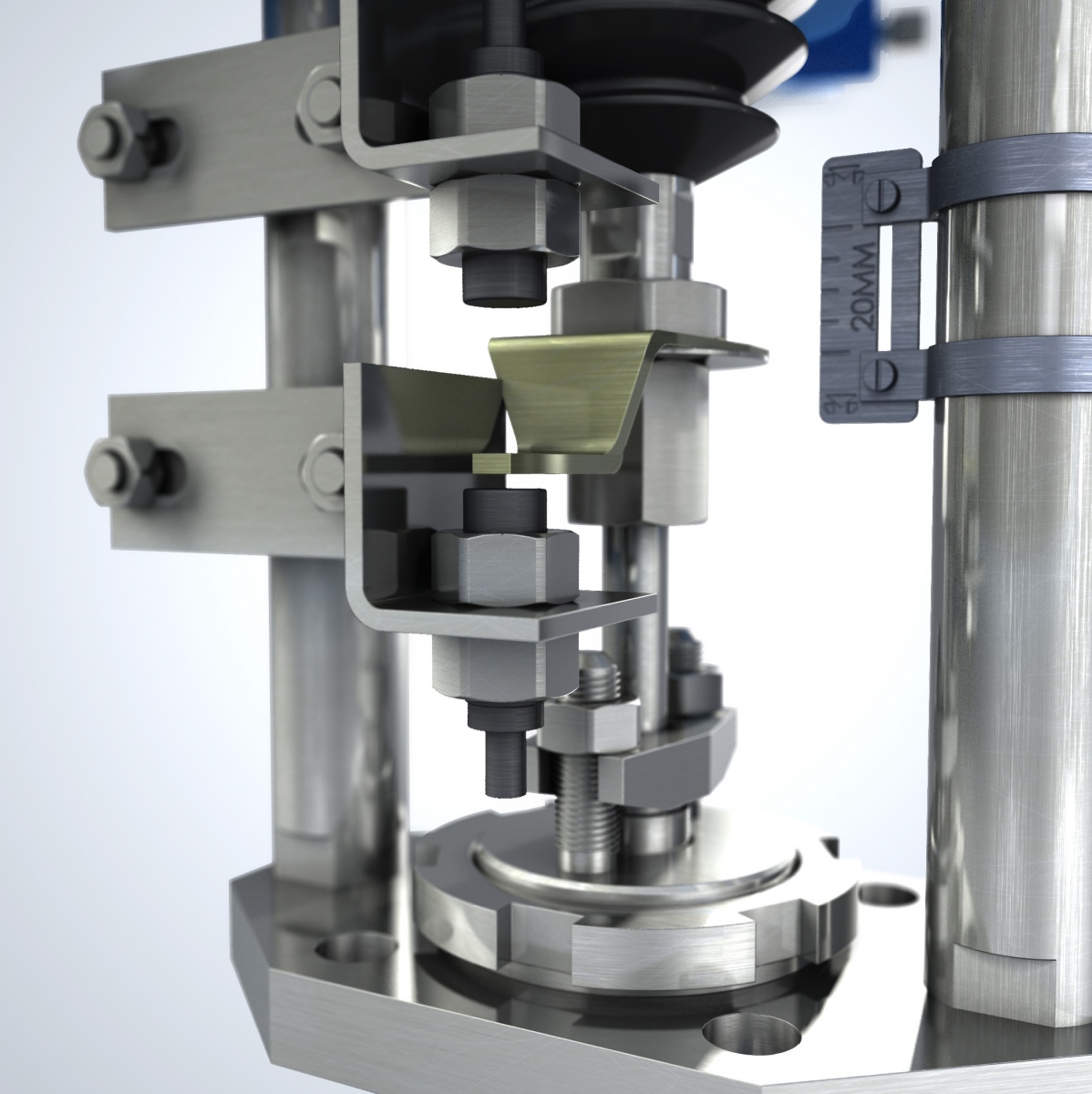
When, under special circumstances, it is not possible to automatically switch a valve that must be opened or closed, the valve can be actuated with the manual drive, which is an accessory of the actuator (Fig. 3, 4 and 5) or installed directly on the valve (Fig. 6). Manual drives can also serve as stroke limits.
Fig. 3. Control valve with a linear pneumatic actuator type P/R and a top-mounted manual drive.
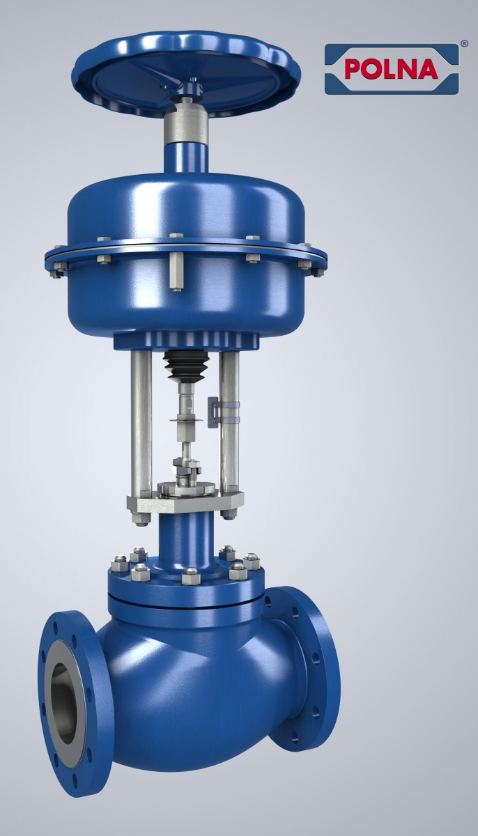
Fig. 4. Multi-spring pneumatic membrane actuator type P1/R1 with a side-mounted manual drive.
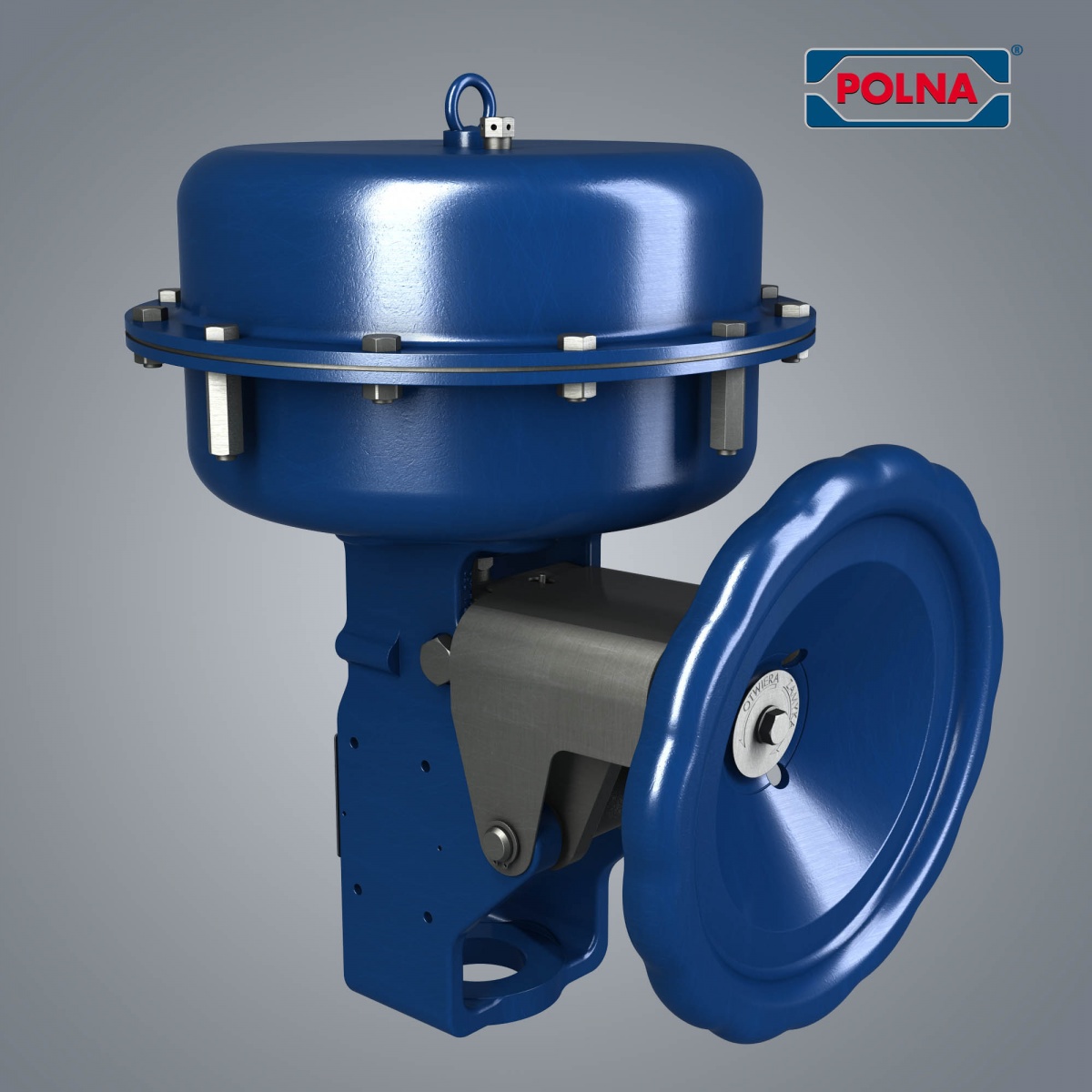
Fig. 5. Multi-spring pneumatic membrane actuator type R1B-3000 with a side-mounted manual drive.
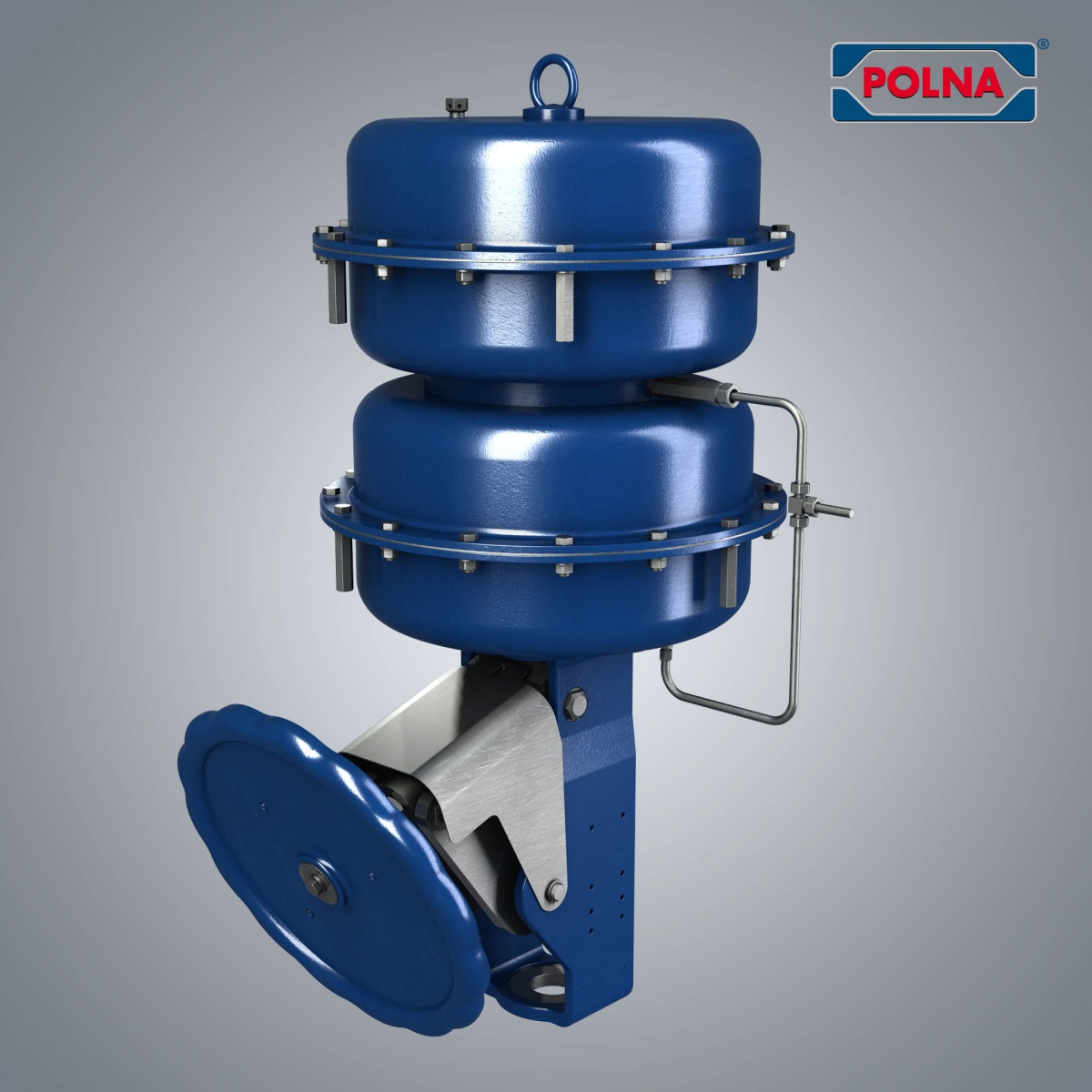
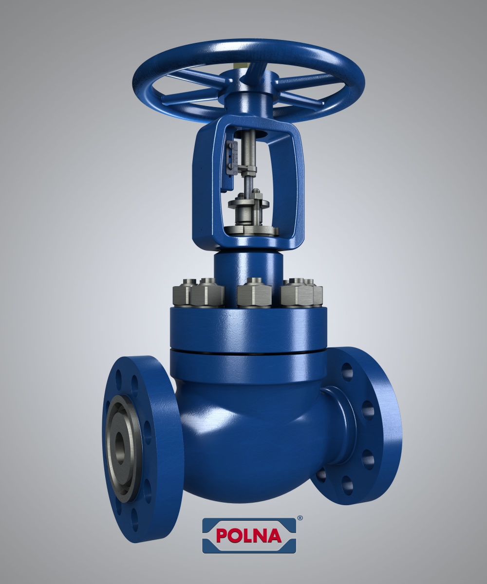
Fig. 6. Control valve with the manual drive type 20.
The choice between electric, pneumatic and piston actuator most often depends on the plant requirements and availability of appropriate power supply types. Sometimes the actuator type depends on customer’s requirements and preferences.
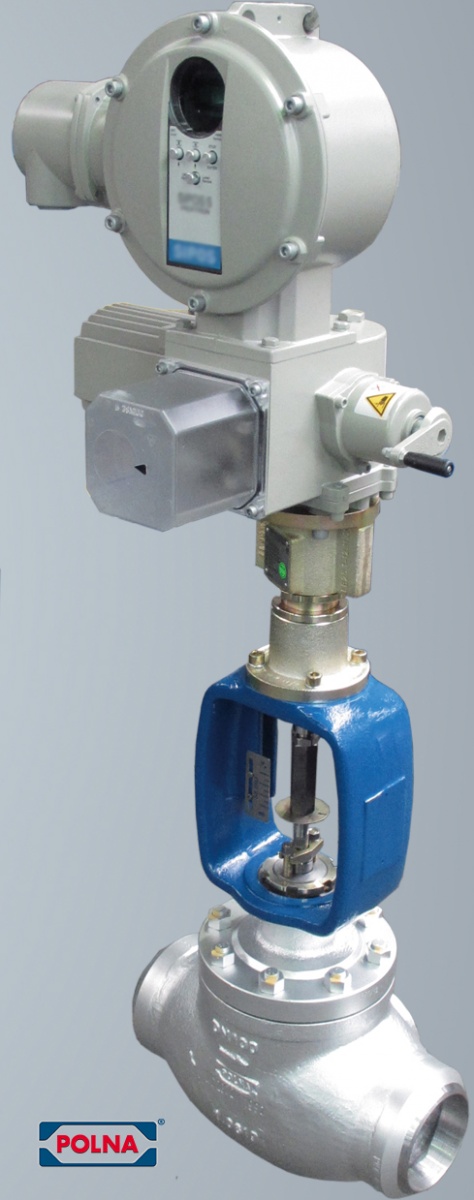
The following shows the control valves with the latest generation of electric actuators.
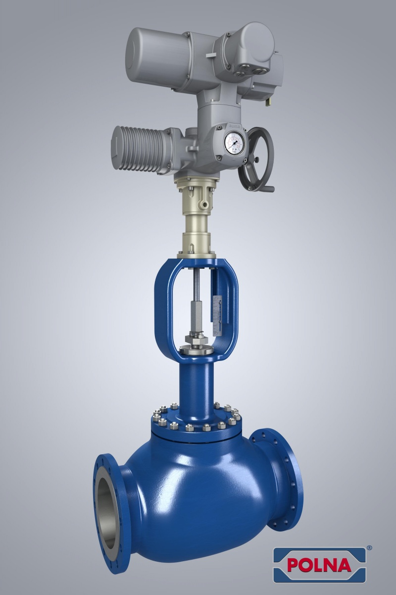
POLNA S.A. is a specialist in the selection and manufacturing of control valves for heavy industries, especially in power engineering, gas engineering, petrochemical and chemical sectors.
We invite you to cooperation.